Product Description
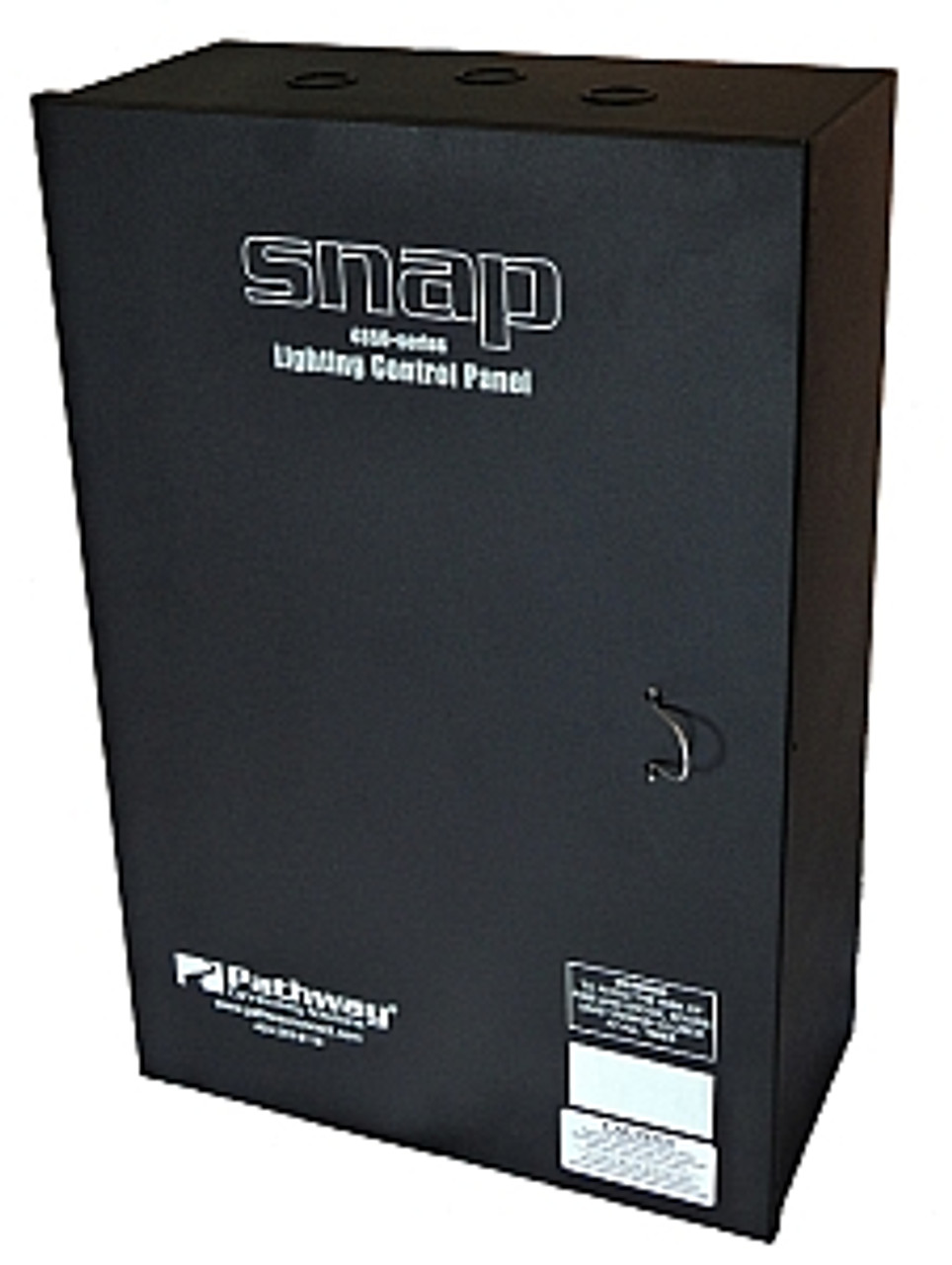
Pathway Connectivity PWRLY R8 8-Channel SNAP LED Control Panel (Old Part #4850-8)
The new SNAP lighting control panel provides unified DMX512 control of 0-10V analog outputs and relay switching, all within a single enclosure. Intended for use with fully isolated LED fixture drivers requiring mains switching and 0-10V dimming, and for Mark VII type electronic fluorescent ballasts.
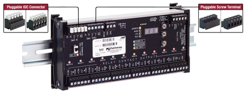
Each SNAP panel consists of an LC&D GR1400-series Blue Box relay panel with a Pathway Connectivity eDIN SNAP Panel Interface card. The interface provides single DMX channel control over the relay and analog output pairs, or allows separate DMX control of relays and analog outputs. The interface also provides a full, non-sequential DMX soft-patch for maximum flexibility.
IMPORTANT NOTICE: Pathway has determined that some LED luminaire manufacturers are providing non-isolated fixture drivers with non-Class 2, 0-10V dimming options. The #1004 is not intended for use with non-isolated or Class 1 fixture drivers. Please review the Technical Bulletin in the download chart below, or download the document here. Use of the #1004 with non-isolated drivers may result in damage to the #1004. This damage is not covered under warranty.
UL924: When connected to the emergency transfer circuit, the SNAP panel will perform normally, and circuits may be triggered using the AUX IN dry contact control. For best operation, AUX1 and AUX2 are jumpered together and a maintained contact is provided by the panel between AUX1/2 and COM. When the maintained contact is broken on return to normal operation, the panel will be restored to DMX control.
If the panel electronics are not connected to the emergency transfer circuit, the panel is designed to fail with the relays closed and the analog outputs open (full intensity). Please note that any mix of emergency and non-emergency circuits is governed by local codes.
Features
- Eight or sixteen normally-closed (NC) single-pole latching relays
- Sixteen analog 0-10V outputs
- Easy, front panel configuration
- LED indicators for Power, DMX IN, processor and relay state
- Adjustable DMX start address, or each output may be assigned a non-sequential DMX address
- Analog outputs may be paired with relays for unified single DMX channel control, or control of relays and analog output may be split by assigning different DMX addresses to each
- Outputs may be patched to Auxiliary Input dry contact inputs
- User-settable relay trigger thresholds
- Test features include on-board relay test and review of incoming DMX levels, on a channel-by-channel basis
- DMX Thru connector and termination switch
- Discoverable and configurable using RDM
Specs
- Normally Closed (NC) Single Pole Relay ratings:
- 30A @ 277VAC Ballast
- 20A @ 120VAC Tungsten
- 20A @ 347VAC Ballast
- SCCR 18kA @ 277VAC
- Rated for 250,000 cycles
- 120V/277V transformer line voltage input
- Mixed voltages allowed in cabinet in accordance with NEC and local code requirements
- Analog Outputs rated for 100mA per channel, sinking control
- Analog Outputs rated for 10mA (ten mA) per channel, sourcing
- Operating Conditions: 32°F to 104°F (0°C to +40°C), 10-90% relative humidity, non-condensing
- 27.0 lbs (12.25 kg)
- 12.0”W x 18.0”H x 6.0”D (305mm x 460mm x 150mm)
- Compliance
- ANSI E1.11 DMX512-A
- ANSI E1.20 Remote Device Management (RDM)
- ANSI E1.3 0-10v Analog Control
- ANSI C82.11 Fluorescent Ballast Control
- UL, UL924


