Product Description
WE ARE CURRENTLY WORKING TO FIND A SOLUTION FOR THIS REPAIR.
Leviton discontinued repairs on this product in January 2024. We might be able to help you with an alternative solution.
Please call us at 1-866-457-5937 with any questions.
These repairs can take up to 4-6 months to complete.
***************************************************
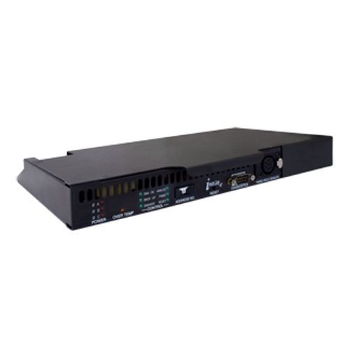
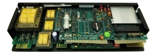
Leviton Colortran iSeries i48/i96 Control Module, REPAIR
Part #4-0311 - Control Module 120V, repair
(A Repair requires that you ship out your malfunctioning unit, per instructions provided via email.)
Part #CTP-4-0311, repair.
This is the repair of an existing Leviton Colortran iSeries i48/i96 Control Module with part #CTP-4-0311.
Once you place the order, we will send you an RMA# and shipping instructions to ship your control module for repair.
The control module will be repaired within 2-business days of receipt and then overnight return shipped to you.
It is your responsibility to ship the control module out for the repair according to the directions provided.
If you need assistance removing your control module from the dimmer rack, then please call us at 1-866-567-5937.
Additional information on the 4-0311 control module:
1.1.1. Control Modules
1. The Control Module shall be a plug-in assembly consisting of a formed steel chassis, one glass epoxy printed circuit board, and two levers for easy tool-free insertion and removal. Control Modules shall contain LED's providing user feedback. Racks using non plug-in control modules or electronics requiring the removal of panels for servicing are not acceptable.
2. Each rack shall contain an electronic backplane, with all control wiring connections on removable screw terminals for easy control wiring.
3. Each rack shall require only one control module. A slot shall be provided in the rack for a second, fully redundant on-line (Backup) control module. In the event of the Main control module's failure or removal from the rack, the Backup control module shall automatically maintain proper rack operation without any noticeable change to current lighting conditions. Systems that do not provide for a fully redundant on-line Backup control module or require user intervention to bring the Backup control module on line, are not equal and not acceptable.
4. The backplane shall retain all rack configuration and Backup Looks in non-volatile memory, so that when any new control module is inserted, it automatically comes on-line, fully functional within ten seconds without requiring any programming by the user.
5. Each rack shall contain a single control module that connects to the rack’s electronic backplane.
6. Control modules shall be inserted and removed without the use of any tools.
7. An On-line button on the control module shall be used to select the active control module at any time.
8. Each control module shall have three LEDs to indicate the presence of voltage on each power phase.
9. The control module shall contain a slot for a PCMCIA memory card, and Read Card and Write Card buttons.
10. The rack configuration and all 99 Backup Looks shall be able to be stored on a memory card for quick access to archived configurations.
1.1.2. Functional
1. The modules shall utilize completely digital electronic circuitry including high speed microprocessors for performing dimmer level calculations and feedback communications. The control modules shall automatically accept either Colortran protocol (156K baud) or DMX 512 protocol (250K baud). All control data inputs shall be optically isolated to 4,000V.
2. The Control Modules shall have On-Line and power LED's for each phase, visible from the front of the rack. The power LED's shall indicate if any phase is missing or incorrectly wired.
3. Each control module shall accept two input control signals of either the industry-standard DMX512 or Colortran (CMX) protocols. Through these inputs, up to four dimmer data sources can be combined and completely remapped through a user prioritized “highest takes precedence” soft patch.
4. A ColorNet© network interface for dimmer and feedback data shall be provided. Each control module's front panel shall provide an RS232 serial port, a Hand Held Terminal port, and a PCMCIA slot.
5. The rack shall be able to be configured through a DOS-based application running on a personal computer connected to a control module’s serial port.
6. Each control module will allow for back-up and library storage of the rack's configuration and back-up looks through the use of an industry standard 1MB PCMCIA Memory Card.
7. The Rack Control Module shall have at least eight 0-10 V DC optically isolated analog inputs which can be patched to one or more of the 24 dimmers in the rack. A memory transfer input shall be provided to switch between digital and analog control of these dimmers.
8. While connected, the PC shall be able to access and edit all of the rack’s configuration parameters, and receive dimmer feedback information in real time.
9. Provision for a Hand Held Terminal shall also provide access to configuration and feedback information.
10. Each Control Module shall have the following user-programmable Configuration Features:
a) Line Voltage Regulation Speed: fast(20ms), slow (200ms), or off (unregulated), per dimmer.
b) Control Response: fast (20ms) or slow (200ms), selectable per dimmer.
c) Minimum and Maximum Level per dimmer as a percentage.
d) Electronic Noise Reduction feature enable/disable per dimmer.
e) Unregulated Non-dim function per dimmer.
f) IES square law (modified) or one of five user-programmed output curves.
g) Cable resistance values for each dimmer.
h) Complete Patch (remapping) and Pile-on Priority Functions from multiple dimmer data sources.
i) Over-temperature warning level
6. Each dimmer shall provide feedback to the control module, which in turn sends the information to any of three different user interfaces:
a) The Hand Held Terminal
b) A PC plugged into the control module
c) A Video Peripheral Controller (VPC) and monitor on the ColorNetã network.
7. Configuration can be downloaded from a PC attached to the serial port of the control module or via the ColorNetã network. The Control Module shall be able to receive, process, and distribute information both from local sources and from and to the ColorNetã network.
8. Feedback information shall also appear through the LEDs of each dimmer module. Feedback information for each dimmer includes the following elements:
a) Active load
b) Active voltage
c) Error conditions:
-deviation from recorded load
-open circuit (no load)
-tripped circuit breaker
-over-temperature warning
-over-temperature shutdown
-Panic condition
-incorrect module for selected rack position
9. In addition to feedback from each dimmer, the rack shall monitor and provide feedback for the active voltage per phase and total power consumption over time in kW/hr.
10. Each rack shall come with hardware-selectable Panic operation for each dimmer.
11. Terminals for dry contact closures shall be provided to initiate a Panic condition, which drives all selected dimmers to full without affecting any other control settings. When all control modules are removed from the rack, the selected Panic dimmers shall go to full and all other dimmers shall go to zero.
12. Each rack shall have an optional Hand Held Terminal. Rack configuration, direct control of dimmers and Backup Looks, and dimmer feedback shall all be achieved through the Hand Held Terminal.
13. In Multi-rack installations, one or more Hand Held Terminals shall be able to operate simultaneously to access and edit dimmers system wide.
14. The Hand Held Terminal shall be capable of wired operation up to 1000' from the dimmer rack. An optional wireless Hand Held Terminal shall be available. The unit shall use spread spectrum RF technology.


