Product Description
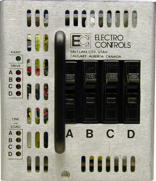
DMX conversion kit for Electro Controls “Playmate” digital 12 x 2.4KW packs
The JS-EC12P is a direct DMX 512 retrofit controller specifically designed for facilities with an existing Electro Controls (EC) Portable Playmate dimmer packs. This product will upgrade existing dimmer packs to current dimming technology in minutes. The EC12P is pin to pin compatible with O.E.M. factory wiring for ease of installation. DMX input and state-of-the-art high speed processing make upgrading these ruggedly built "work-horse" dimmer packs fast, simple and inexpensive!
JS-EC12P Features
- Direct "plug-in" retrofit compatible with OEM dimmer pack wiring.
- DMX addressing and configuration accessible via the original face panel.
- New "self-adhesive" face panel overlay provides accurate upgraded information.
- DMX input XLR connectors (IN and THRU) pre-wired to "break-away style" connectors permit fast and easy installation.
- Hi-speed processor ensures accurate dimmer output levels and smooth fades.
- LED Status indication of power, data receive and over-temp.
- Face panel "DMX Termination" and "Panic" switches.
Specifications:
1.1 Direct replacement design of the unit shall make installation fast and easy. The controller shall contain the main processor and all ancillary control electronics for the dimmer pack.
1.2 Dimmer control outputs shall be designed for precise and reliable control of the existing EC Playmate portable dimmers. It shall never be necessary to adjust ramp circuits for proper dimmer output.
1.3 The control electronics shall be capable of controlling up to 12 dimmers in the EC Playmate dimmer pack.
1.4 The units shall accept DMX512-A digital data protocol allowing industry wide compatibility with most control consoles. DMX input and DMX thru connectors shall be provided on the face panel of the controller.
1.5 End-of-line DMX termination shall be selectable via a face panel switch.
1.6 A face panel "panic" switch will permit instant activation of all dimmers to full regardless of input control.
1.7 The controller shall include an LED indicator for power supply and microprocessor status. The LED, when illuminated, shall indicate normal operation, and when flashing shall indicate a hardware fault. A power supply or power failure, shall cause the LED to extinguish.
1.8 The controller shall include an LED for data receive indication. Loss of valid DMX512 data shall cause the LED to extinguish.
1.9 The controller shall incorporate fan control circuitry designed to interface with the OEM wiring. Controller software will allow for an additional five (5) minutes of air evacuation from the dimmer pack with loss of input control signal.
1.10 In the event of a dimmer "over temperature" signal, the controller will activate a "OT" red LED on the controller face and disable all dimmer outputs.
Specifications subject to change without notice.


