he Lightronics replacement wall control station system works well and we have used this system on many projects.
You MUST replace all of the wall control stations at the same time.
LIGHTRONICS WALL STATION, REQUIRES A MASTER & REMOTE STATION(S) WHEN USED WITH DMX CAPABLE DIMMERS OR LIGHTS
A great option for replacing NSI 400/800 CP stations is the Lightronics Control System, which could use a 4-conductor digital control wire. The Lightronics control stations fit into standard 1-7 gang back boxes.
The Lightronics Control System is capable of controlling up to 512 dimmers or a full universe of DMX.
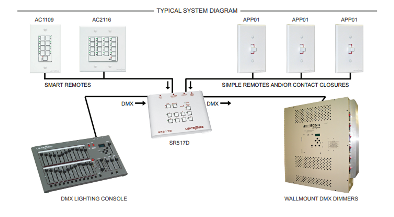
The Lightronics Control System would have one (1) Lightronics Master Control Station that would do three things:
A) Take in DMX from a Desktop Lighting Console for DMX snapshot of dimmer values to scenes on the master station (passing through the DMX to the dimmer rack).
The Master Station then shares its scenes with the Lightronics Remote Control Stations.
B) Take in/out the communication to the Lightronics Remote Control Stations.
C) Output DMX to the DMX Controllable Dimmers and/or lights in the system.
The Lightronics Remote Control Stations will activate the scenes on the Lightronics Master Control Station.
The Lightronics System will allow you to have as many control stations as needed (within power supply limit), all working together on the same system.
For example, you might have one Lightronics Master Control Station and five Lightronics Remote Control Stations.
MASTER CONTROL STATION - JUST ONE IN A SYSTEM - NEXT TO DIMMER RACK
The Lightronics Control System would have one (1) Master Control Station (typically).
Here are the options for a Lightronics Master Control Station (choose just one):
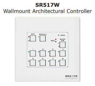
1) Lightronics SR517W Master Control Station (11 Buttons, Wall Mount, 2-gang)
2) Lightronics SR517D Master Control Station (11 Buttons, Portable Desktop)
3) Lightronics SC910W Master Control Station (10 Sliders, 11 Buttons, Wall Mount, 5-gang)
4) Lightronics SC910D Master Control Station (10 Sliders, 11 Buttons, Portable Desktop)
The manual for the Lightronics SR516(7)W/D can be found at the following link: https://www.lightronics.com/manuals/sr517m.pdf
The manual for the Lightronics SC910W/D can be found at the following link: https://www.lightronics.com/manuals/sc910m.pdf
**All of the Control Stations on the same control wiring MUST be replaced at the same time.**
You cannot leave some of the control stations as one manufacturer and then have other control stations as another manufacturer. This will not work.
REMOTE STATIONS - ALL BUT ONE MASTER CONTROL STATION
The Lightronics Control System would then have as many Lightronics Remote Stations as you want (within the limit of the power supply, can add more power supplies).
The Lightronics Remote Control Stations would connect to the Master Lightronics Control Station through a 4-wire digital control cable (such as the existing Lumanet I control wiring).
You could purchase any of the following Lightronics Control Stations as Remote Stations:
1) Lightronics AF2104 (4 Faders) Architectural Remote Station (2-gang) 
2) Lightronics AK1002 (2 Buttons) Architectural Remote Station (1-gang)
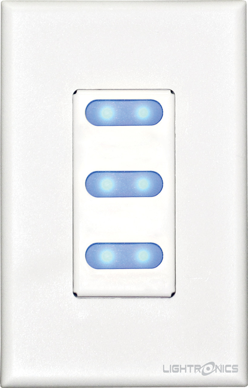
3) Lightronics AK1003 (3 Buttons) Architectural Remote Station (1-gang)
4) Lightronics AK1005 (5 Buttons) Architectural Remote Station (1-gang)
5) Lightronics AC1109 (9 Buttons) Architectural Remote Station (1-gang)
6) Lightronics AC2116 (17 Buttons) Architectural Remote Station (2-gang)
7) Lightronics AF5113 (13 Faders) Architectural Remote Station (5-gang)
8) Lightronics AF3107 (7 Faders) Architectural Remote Station (3-gang)
9) Lightronics AI1001-Architectural Infrared Remote Station (13 scenes) (1-gang)
10) Lightronics AI1001-Port01-Architectural Infrared Remote (with optional Port01) (13 scenes) (1-gang)
11) Lightronics AX0009-8 Scene Remote Interface (8 scenes, hardwired contact closures)
The Lightronics Remote Control Stations can use the existing Lumanet I wiring that is either going directly to the dimmer racks or a Leviton NSI IF501, assuming the cable is daisy chained and is the correct cable.
If the Lightronics Remote Control Stations are 2 gang, then they just use the existing back box.
If the Lightronics Remote Control Stations are 1 gang, then you can use a reducer ring, such as the Johnson Systems PA-2A1 2 Gang to 1 Gang Adapter Plate.
LIGHTRONICS CONTROL STATIONS CAN USE 12-16VDC POWER SUPPLY
You can use the existing power supply for the NSI 400 or 800 CP Control Stations to power the new Lightronics Control Stations.
OR
You can use the Lightronics Power Supply.
LIGHTRONICS REMOTE CONTROL STATION WIRING TO THE LIGHTRONICS MASTER CONTROL STATION
You will need to lift the existing Lumanet I control wiring off of the dimmer racks and move to the Lightronics Master Station's Remote Wiring location.
The Lumanet I wiring would connect to the Remote Input Port on the Master Control Station.
Here is the manual for the Leviton NSI 2408 Dimmer Pack (typical dimmer): https://goknight.com/leviton-nsi-cd2408-manual/
If you go to page 6 of 10 on the manual, you will see the Power Supply I/O Card.
With existing Lumanet wiring, the control wires will be on Rem+, Rem-, +15v, and Common. The control wire should be a 4-conductor with a shield.
1) Lumanet I REM+ from the Dimmer Rack is lifted and goes to REM+ on the Lightronics Master Station.
2) Lumanet I REM- from the Dimmer Rack is lifted and goes to REM- on the Lightronics Master Station.
3) Lumanet I DC Common gets extended from the dimmer rack to the DC Common on the Lightronics Master Station.
4) Lumanet I +15vdc gets extended from the dimmer rack to the +12v on the Lightronics Master Station.
The manual for the Lightronics SR516(7)W/D can be found at the following link: https://www.lightronics.com/manuals/sr517m.pdf
The manual for the Lightronics SC910W/D can be found at the following link: https://www.lightronics.com/manuals/sc910m.pdf
On page 4 is a wiring diagram between the Master Station and the DMX (out) going to the NSI 2408CD Dimmer Pack, lower left-hand corner of the page.
On page 5 is a wiring diagram between the Master and Remote Station with the 4-conductor wiring (already have that wiring).
**All of the Control Stations on the same control wiring MUST be replaced at the same time.**
You cannot leave some of the control stations as one manufacturer and other control stations as another manufacturer. This will not work.
LIGHTRONICS DMX INPUT WIRING TO MASTER CONTROL STATION
You will want to route the DMX from your Desktop Lighting Console to go into the DMX input on the Lightronics Master Control Station.
This will allow you to use your DMX capable Desktop Lighting Console to program the scenes on the Lightronics Master Control Station.
We can provide options for cost effective Desktop Lighting Consoles. This is the easiest way to program a Lightronics Master Control Station.
LIGHTRONICS DMX OUTPUT WIRING FROM MASTER CONTROL STATION TO DMX CAPABLE DIMMERS/LIGHTS
You will want to route DMX from the Lightronics Master Control Station to the DMX capable dimmers and/or lights.
This will then allow both the DMX Capable Lighting Console and the Lightronics Master Control Station to control the same dimmers and/or lights.
The Lightronics Remote Control Stations will route their scenes through the Lightronics Master Control Station and to the dimmers and/or lights.
LIGHTRONICS SIMPLE CONTACT INTERFACE - MASTER STATION INPUT
The Lightronics Master Control Station also has simple contact inputs 1-3 that allow any dry contact switch to operate scenes 1-3.
This is a very simple control system and does NOT have a digital control signal, but rather has an analog control signal.
You will just need 2 wires to trigger each scene. So that if you have a control station with 3 dry contact buttons, you would need 4 wires (common and 3 scenes). The 3 three dry contacts trigger the 3 scenes on the Master Control Station. Each dry contact input will need 1 wire, which would be 3 wires for 3 dry contact inputs. Then you can run either 3 separate common wires, one for each dry contact input or you can run a “shared” common wire. This means that you could have a total of 4 or 6 wires, depending upon a shared common wire or a separate common wire for each dry contact input. This can be confusing, so that, if you want to use the dry contact inputs, please contact us for additional assistance.
1) Lightronics APP01 Architectural Simple Remote Station (1-gang)
Please feel free to reach out to us for additional information about replacing your NSI Lumanet Stations with the Lightronics Unity control system.


